SEM 52A Information
By Alan Tasker atasker@ix.netcom.com and others.
|
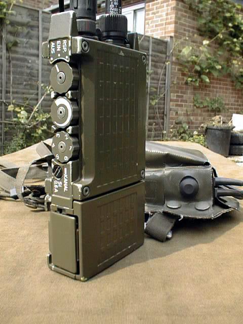
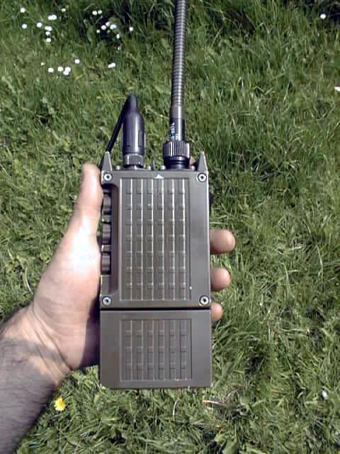
Overview The SEM 52-A is a cute, small, 6 channel, low power ( 300 mW ) Military portable of German build ( SEL ) that comes with an awkward looking ( my opinion ) head piece containing a tiny speaker and a bone conduction microphone. It runs from 6 ea penlight cells, and has a spare battery pack in its shoulder worn carry case ( tape antenna also included ). It is available from a couple of renowned surplus dealers. Nobody has come up with any documentation yet, so it takes some fitzing and futzing to try to figure things out. Jane's
states that it is a narrow band FM unit, so you're not going to get loud audio when it
transmits if you want to re-crystal it to use with US mil gear. However, wideband audio is
received pretty well in the un-squelched mode ( EIN ). One thing to note is that in the
squelched mode ( RSP ), the receiver is pulsed on for 50 ms every 250 ms It usually comes set up with two channels, 47.8 and 55.5 MHz. The crystals are Fch + 20
MHz, and they are attached to their own special element board containing the crystal, Models |
|
|
|
H-250 Handset Conversion
Kim Campbell was nice enough to send me Mark Gluch's H-250 conversion. I wondered if
there wasn't an easier way if you wanted to give up on both the side tone and the 150 Hz
CTCSS function ( my next project is to put a CTCSS board internal to the unit ). There is
an easier way, so now I have to get some of the male connectors that interface to the
H-250 handset. Anyway, the following info is about the SEM 52 audio connector. Pin
"A" is closest to the red dot or line. Progression is clockwise from the top of
the unit connector. The first colour is the wire colour inside the PTT box, ( while the
second colour is the colour inside the unit ). Be careful your colours may vary. Mark and
I have one wire a different colour. "G" is the centre pin, A magnifying glass
helps.
 SEM 52 Headset wiring diagram. Connector pins viewed from pin side |
|
Pin Label |
SEM 52 Audio Connector Pin-Outs |
| A | Ear Piece, Yellow, ( Green ). Ear Piece impedance 150 Ohms |
| B | Ear Piece, White, ( Blue ) |
| C | Mic hot, centre of the shielded wire in both cases ( could be Red, White, or ??? ). |
| D | PTT, Green, ( White ) |
| E | Unknown, ( Yellow ) |
| F | +9 Volt for bone condition Mic, Brown, ( Red ) |
| G | Mic low, Shield in both cases |
| G | PTT Return, Grey ( Shield ) |
The surprise is two wires for the ear piece. There has to be an ohmic connection between yellow and white or the audio goes away. In addition, the DC level is up at 9 V. So, here is what you do.
| H-250 Pin-Out | SEM 52 Pin-Out |
| H-250 Common ( A ) | To Shield, Pin ( G ) |
| H-250 Microphone ( D ) | To Pin ( C ) |
| H-250 PTT ( C ) | To Pin ( D ) |
| 1K Ohm Resistor between Yellow and White, A and B | |
| Capacitor Negative side to H-250 ear piece ( B ) | 4.7 uF 16 Volt Capacitor, Positive side to ( B ) |
|
Inside The SEM 52A If you take both covers off ( Metric bolts ), here is what you see. Let's define the "up" as the side where we can view the body of the on / off switch and the volume control. There are several shielded items on this side. My experience / assumptions are as follows.
|


L16, L17, L18 is a input / output band pass filter.
The red coated assembly is the Mic Amp.
L1, L2, L3, L5 is an FM modulated 20 MHz oscillator.
The tiny bare assembly is a doubly balanced mixer.
L6, L7, C21, C14 is mixer post filtering.
C41, L9, C44 is the final power stages.
The shielded entity closest to the battery box is the oscillator for the main frequency
determining crystals. The ones on the element boards in the rotary channel selector
switch.
R1 is a Mic Amp level control. CCW is max.
R37 adjusts the output power level.
On the reverse side is one large shielded board which is the receiver.
R12 is the squelch control.
R9 controls max audio level to the volume control.
|
The SEM 52 is VVC ( voltage variable capacitor ) tuned. There is a DC-to-DC converter assembly that creates about 20 Volts, and that is applied to the high end of the voltage divider on the crystal element board. The correct divider must be there to tune the radio for that particular crystal frequency ( for example, replacing the 55.5 MHz crystal with one for 51 MHz required adding a 33.2 k Ohm resistor from the divider point to ground ). This 20 Volts can be adjusted somewhat by the small pot seen almost obscured by the on / off switch body ( on the front panel side ). This control can be used to optimise the radio's tuning for any one channel, or to balance the tuning for a couple of channels. |

| Operational Frequency | R1 | R2 | Intermediate Frequency = 20MHz 51.00MHz + 20.00MHz = 71.00MHz |
| 51.00 | 56K | 160K | |
| 51.10 | 60K | 160K | |
| 51.20 | 62K | 160K | |
| 51.30 | 62K | 160K | |
| 51.50 | 66K | 158K | |
| 52.00 | 75K | 145K | |
| 53.00 | 96K | 123K | |
| 53.90 | 110K | 110K |
Please E-Mail your comments to Alan Tasker atasker@ix.netcom.com
Additional Information form Jane's
Developed in early 1970s under a Federal German Government contract. Entered service with
the Federal German Army in 1974. Production ceased in 1978 with the planned introduction
of a replacement equipment SEM 52S.
The Transmitter / Receiver sets type SEM 52 are designed for simplex communication and have a range of approximately 3 km. They each provide six or twelve pre-adjustable frequency channels at 25 Khz channel spacing. The output power of the equipment is approximately 0.3 watt: Transmitter and Receiver use frequency modulation ( F3 ) and operate on the same frequency.
| The equipment has the following frequency ranges | ||
| Model | Frequency Range | Number of Channels |
| SEM 52 | 47-57 MHz | 400 Channels |
| SEM 52N | 70-78 MHz | 320 Channels |
| SEM 52-E1 /2 | 39-48 MHz | 360 Channels |
| SEM 52-E1 /3 | 47-62 MHz | 600 Channels |
| SEM 52-E1 /4 | 60-80 MHz | 800 Channels |
The SEM 52 range was conceived to meet all modern tactical requirements. The equipment's can be used as a portable radiotelephone in a harness with band antenna and headset, microphone loudspeaker or handset, or as a fixed radio station ( table-top mounting ) with band or outdoor antenna and microphone loudspeaker, handset or headset.
The equipment is an all solid-state radio telephone set making extensive use of integrated circuits. The equipment is subdivided into unsolderable circuits. No electrical readjustment is necessary when the circuits are interchanged.
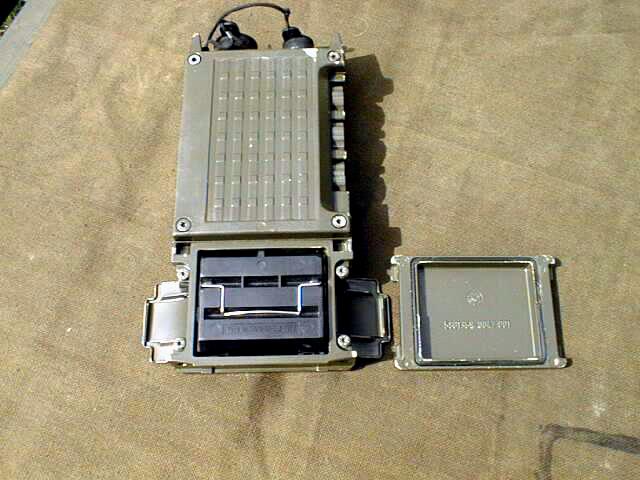
The Transmitter / Receiver and the battery insert are each housed in a separable, water tight cast metal case. The power supply can be provided either by dry cells or by rechargeable nickel-cadmium cells. The equipment contains a channel selector switch, which permits selection of any of the six or twelve pre-set operating frequencies. Other frequencies can be set after changing the channel insert. The controls are on the right-hand narrow side of the Transmitter / Receiver. On the top of the set are the antenna socket and the seven-pole at socket for connection of the headset, microphone loudspeaker or handset.
Accessories include a carrying harness, band antenna, headset / handset or microphone loudspeaker, channel insert holder and battery adapter. By changing the channel inserts it is possible to choose any six or twelve channels from 320 to 800 possible operating frequencies, according to the frequency range, without tuning. The equipment is extremely small and light, and suitable for all forms of tactical application. The SEM 52 set is compatible with the SEM 25 and SEM 35 sets. The mtbf for the SEM 52 and SEM 52N is 4000 hours and for the SEM 52-E1 2000 hours.
Technical Specification |
SEM 52 | SEM 52N | SEM 52-E1 / 2-4 |
| Frequency range | 47-57 MHz | 70 - 78 MHz | 2) 39 - 48 MHZ 3) 47 - 62 MHz 4) 60 - 80 MHz |
| Channel Spacing | 25 Khz | 25 Khz | 25 Khz |
| Number of RF channels | 6 out of 400 Crystal Oscillator | 12 out of 320 Crystal Oscillator | 6 or 12 out of 360, 600 or 800 Crystal Oscillator |
| Mtbf (calculated) | 4000 hours | 4000 hours | 2000 hours |
| Transmitter RF Output | 0.3 Watts | 0.3 Watts | 0.3 Watts |
| Sensitivity for 20 dB (S+N) /N | < 0.4 µV into 50 Ohms | < 0.4 µV into 50 Ohms | < 0.7 µV into 50 Ohms |
| Power Supply | 6.6 - 9 Volts | 6.6 - 9 Volts | 6.6 - 9 Volts |
| Power Consumption on Standby / Receive | 5/35 mA | 7/45 mA | 11 /38 mA |
| Power Consumption on Transmit | 225 mA | 230 mA | 210 mA |
| Battery Life | 15 hours | 15 hours approx. | 15 hours approx. |
| Range | 3-5 km | 3-5 km | 3-5 km |
| Height | 180 mm | 180 mm | 180 mm |
| Width | 85 mm | 85 mm | 85 mm |
| Depth | 36 mm | 36 mm | 36 mm |
| Weight excluding batteries | 600g | 600g | 600g |
| Manufacturer | Standard Elektrik Lorenz AG, Stuttgart. | ||
Visitors to this page since 2 June 1999
Back to Your Articles Index Page.
Army Radio Sales Co. Home Page.